Welcome to my website! I am a computer engineering student at DigiPen Institute of Technology in my senior year. I have worked on several projects while I have been going to college and have featured a few on here. Take a look around, I’ve had lots of fun working on these things. Maybe you’ll like reading about them too.
About
My name is Benjamin Nollan. I love to build and fix things and am currently attending DigiPen Institute of Technology pursuing a Bachelors of Science in Computer Engineering. My main focus of study is Field Programmable Gate Arrays (FPGAs).
From a young age I liked to find out how things work. I would often take things apart to see the insides. My dad works on electronics so naturally I started doing experiments with small circuits.
One of the first projects that I built was a “singing” electric arc. It uses a high voltage transformer powered by a custom driver circuit to create a high voltage arc. The duty cycle of the PWM going to the transformer is varied by an audio signal to create music from the arc.
In college I’ve been learning all of the math and physics models that describe all of the components that have been black boxes. This has brought about thinking of how to do things better.
Daltonismo
Daltonismo – An HDMI Color Blindness corrector.
This was my project for Junior year at DigiPen Institute of Technology. The purpose is to apply color filters that help people suffering with certain kinds of colorblindness more easily differentiate the colors that appear the same.
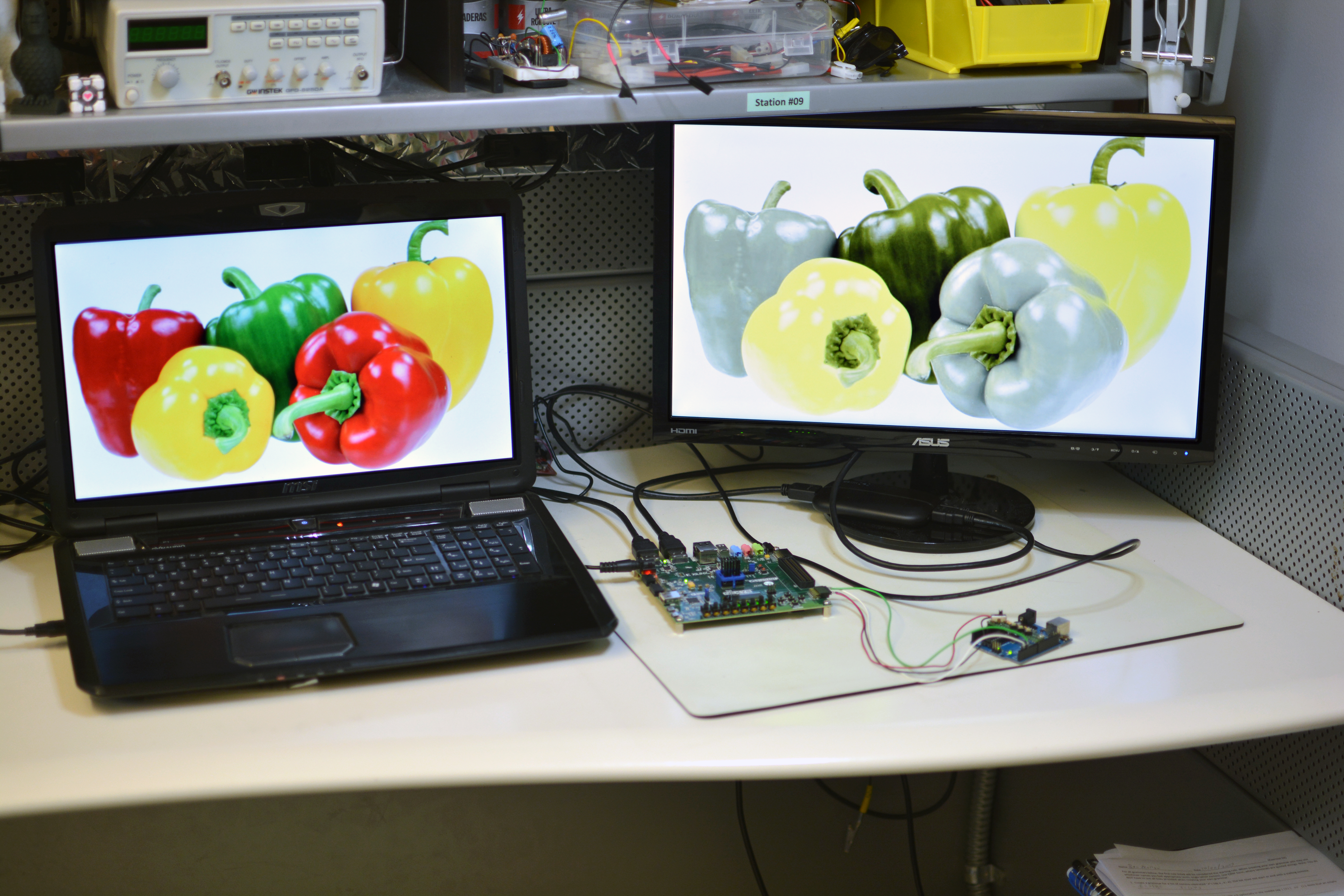
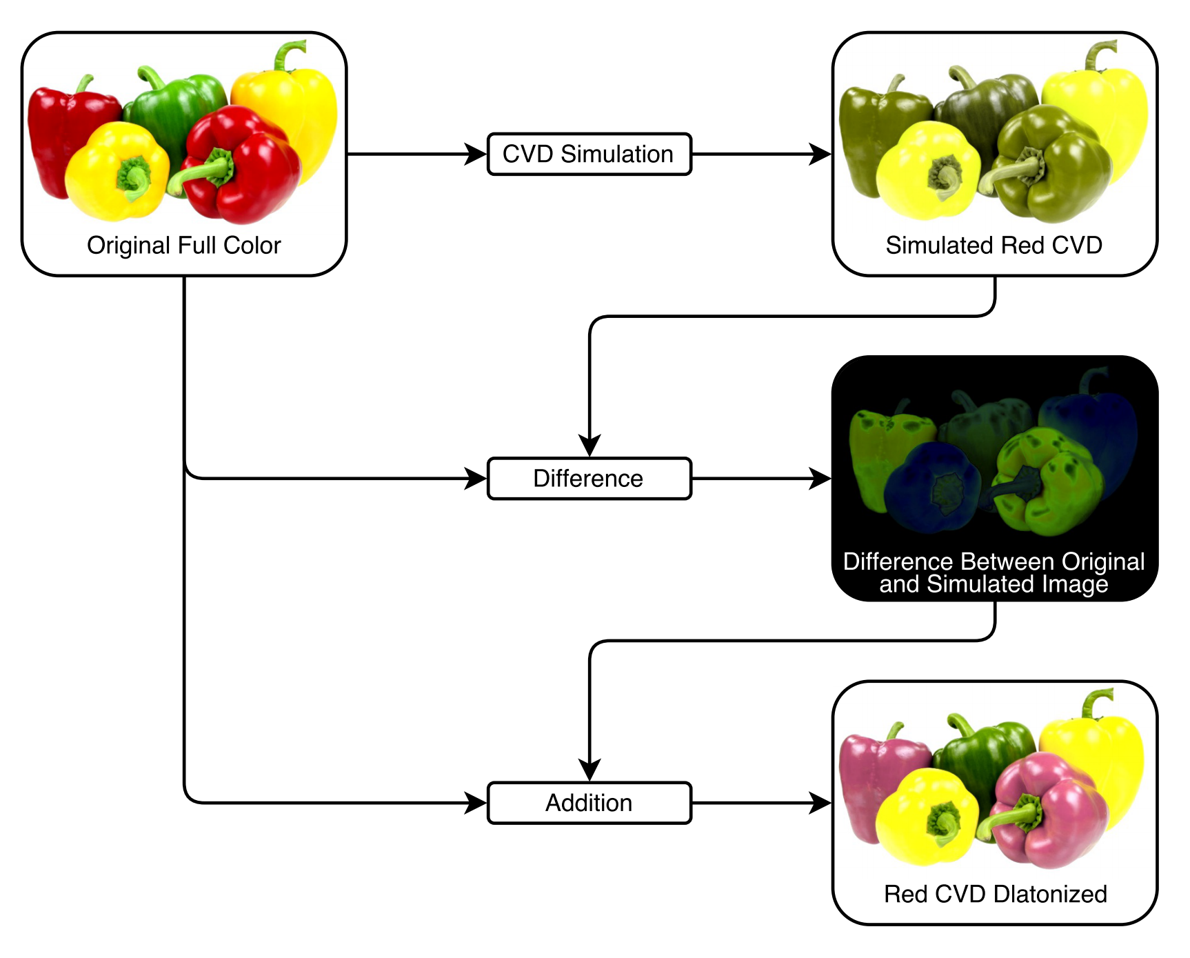
The following images show Daltonization being applied. All of these were captured from the output of Daltonismo.


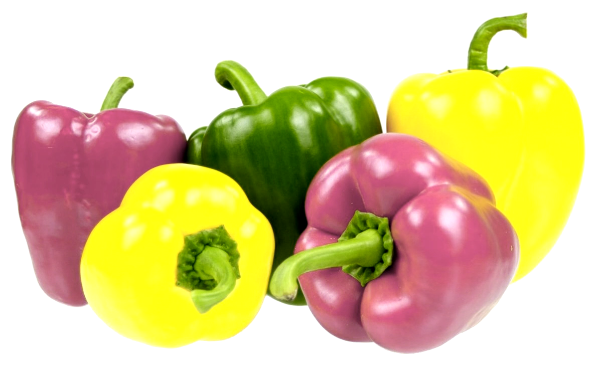
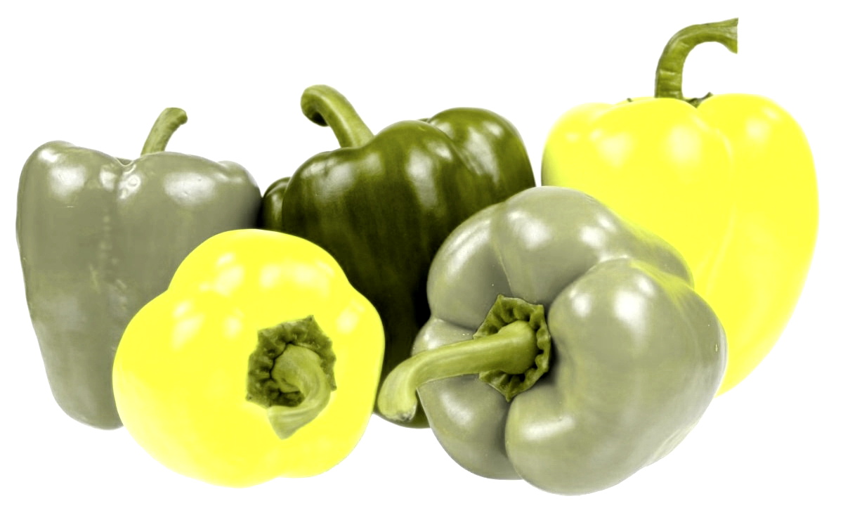
By applying the Daltonization filter on the image, the red and green peppers become more differentiable to an individual suffering with deuteranopia. Lets look at some color gradients to get a better idea of what’s changing.


The Daltonization transformation increases the lightness of the reds and decreases the lightness of the greens. This makes objects of similar brightness that are red and green easier to tell apart, helping separate the similarities.
The color filters are applied using 3 three-dimensional affine transformation matrices. Two of these are used in the process of applying a color blindness correction and the third is used to optionally simulate color blindness.
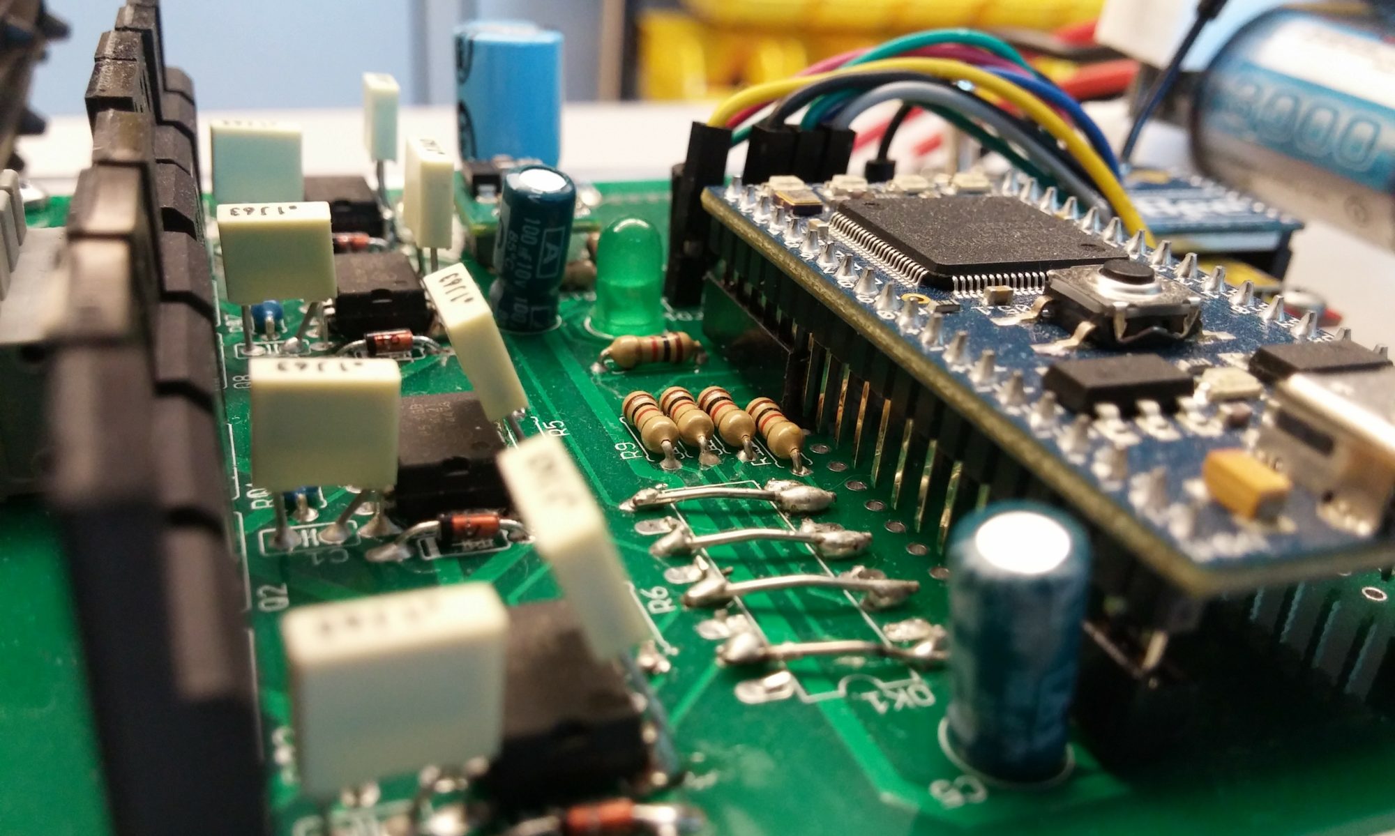
The HDMI decoder and encoder didn’t use any IP modules, in fact, no IP modules were used in the entire project. This makes the project much more portable as it isn’t locked to one particular FPGA manufacturer. For simplicity it isn’t actually an HDMI signal, it is using a fallback mode called DVI (Digital Video Interface). This made the video signal reception easier as I didn’t need to worry about handling audio, control packets, or color space changes.
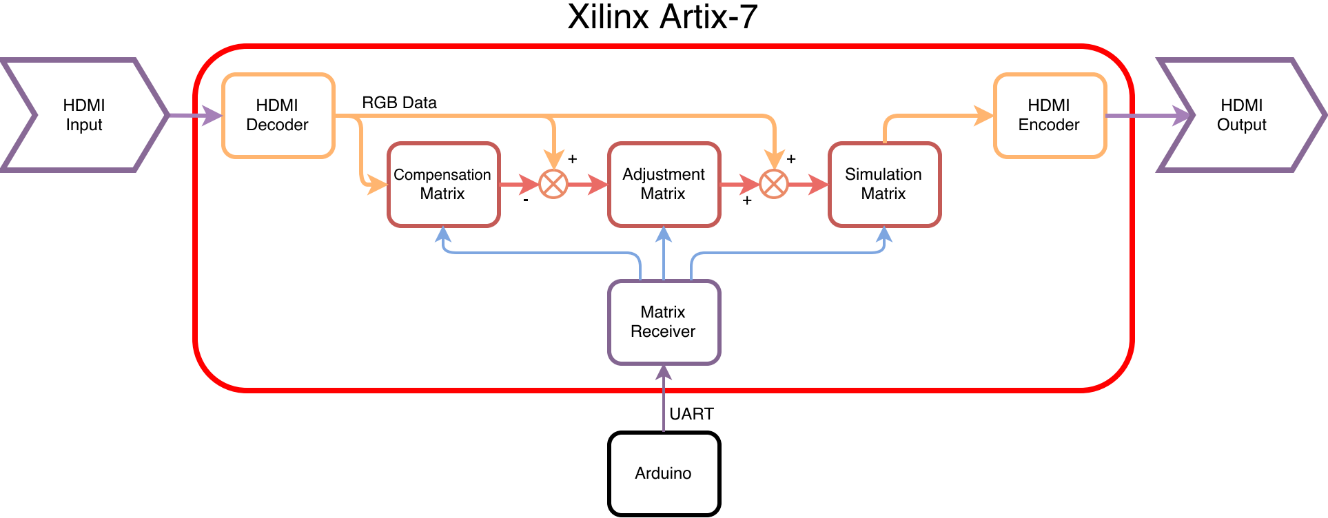
An Ardiuno microcontroller is used to upload matrices to the FPGA on the fly, without any interruption of what’s on screen. This layout made the most sense as it allowed much faster prototyping of new filters as the compilation and upload times of the Arduino are much faster than that of the FPGA. Building and uploading a new version of the Arduino code takes about 10 seconds, compared to the FPGA’s time of around 10 minutes, it made a lot of sense to move the matrix handling to a much more iteration friendly platform.

These devices communicate using a uni-directional UART link operating at 2MHz, which is the maximum speed that the Arduino was capable of outputting. With this high speed link a new possibility opened up, the possibility of uploading a new set of matrices sixty times per second. This meant that every frame can have a different color transformation applied. To synchronize the two a vertical sync signal is sent to the Arduino to trigger the sending of the next matrices. The Arduino was programmed to perform a linear interpolation between the current matrices and the new matrices when switching modes, making the device look much more professional as there isn’t a jarring transition as there would be without the interpolation.
The above video was captured from the output of the project, it shows Daltonization being applied with the linear interpolation. You can see it isn’t perfect as the red peppers get brighter for a little bit. But it’s a nice smooth transition between off and on.
Resume
Contact
The best way to contact me is through my email: bennollan@gmail.com